Stage 3
REALIZATION OF THE PLANE TEXTURED MODELS
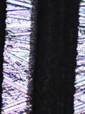
The method used for the realization of the textured tribomodels was the laser ablation technique, extremely versatile. The method implied the utilization of a LUMERA Gmbh laser and of an optomechanical mounting, mounted together with an optical mass.
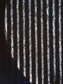
A Nd:YV04 laser was used, laser which has impulses with a duration of tens of picoseconds, designed for microinscriptioning processes using laser ablation, the RAPID type produced by LUMERA Gmbh, Germany. The laser can be used for the ablation of the surface of materials with different compositions and degrees of surface processing, with high precision and with minimum of thermal effects on the surface. Due to the high qualities of the fascicle, the ablation can be realized with lateral resolutions in the field of micrometers and depth resolutions of approximatively 10nm. The realized textures are presented in Fig.1 and 2.
 |
 |
|
Fig. 1. Textures realized by laser
ablation
|
|
 |
 |
|
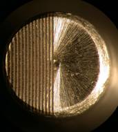
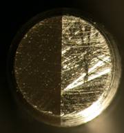
a. Textured
|
b. Step
|
|
Fig. 2. Active surface for the two types of
pins
|
|
INVESTIGATION
Investigation of the depth, width and spacing of the grooves was realized in two ways:
- using a profilometer, which could give the depth, width of the grooves and the distance between the grooves, along a line which is perpendicular to the direction of the grooves
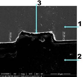
- using an electronic microscope which can give with high precision the transversal profile of the grooves, Fig.3. For this investigation the probe has to pass through a process of preparation which is extremely laborious.
The probe has to be sectioned in order to view the profile of the grooves. A normal cutting process would fill the grooves, exactly in the place of investigation so that the profile of the grooves will be masked.
 |
|
Fig. 3. 1 - material of the probe
(steel); 2 - polimerized material;
3 - transversal profile of the groove |
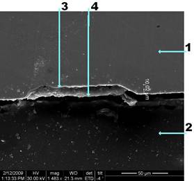
For this reason, before sectioning, the processed surface of the sample is covered by a fluid material in initial state, material which enters in all the grooves until bottom. After polimerization this material becomes hard by adhering very well to the grooved and ungrooved surface of the sample. By transverse sectioning, the grooves are not filled with burred material, Fig.4.
 |
|
Fig. 4. 1 - material of the
probe (steel); 2 - polimerized material;
3 - transversal profile of the groove; 4 - transversal profile of the polimer |
TESTING OF THE PLANE TEXTURED MODELS
The experimental tests, having as purpose the simulation of the hydrodynamic lift, were realized on the universal tester from CETR (UMT), which is in fact a pin-on-disk tribometer having an oil container which reduces the centrifugal effects.
An oil of type 20W-50 having dynamic viscosity η25°=0.315 Pas was used during the tests. The experiments were realized with a rigid pin in order to maintain a constant film thickness during a series of tests. Fig.5 represents schematically the geometric configuration of the contact.
 |
|
Fig. 5. Geometrical model
|
The adjustment of the film thickness was realized for each series of tests in static regime through a capacitive condensator. The tests were realized for three film thickness, respectively 8 μm, 10 μm si 12 μm, Fig.6.
 |
|
Fig. 6. Variation of the normal load with
time
|
A numerical simulation for the validation of the experimental results was realized, Fig.7. A commercial software based on the finite volume method (Fluent Inc.) and a meshing generator (Gambit) were used.
 |
|
Fig. 7. Dynamic dimensionless load function of
dimensionless film thickness
|
PREPARATION OF THE TESTING OF BEARING SHELLS
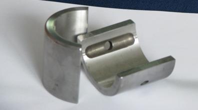
In the frame of the first objective proposed for this stage, two types of shells were prepared for texturing. In order to control the texturing which was realized on cylindrical surfaces, the shells with textured surfaces are composed by two half shells. The testing of these types of bearings is realized after the mounting of the two half shells in a bush, device which functions like a shell with two lobes. In the frame of the second objective for this stage, the calibration and metrological check of the measuring lines in order to supervise the experiments will be realized.
 |
|
|
Fig. 8. Half shells
|
|
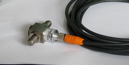
Special attention was given to the proximity measurement devices; their necessity is justified through the possibility, during experimentation, to control the relative position of the shaft and the bush, so the minimal film thickness. Through one of the proximity transducers, the rotation speed of the shaft will be controlled.
The force transducers are other components of the loading-positioning system on which tests and calibrations are realized. They are presented in Fig.9.
 |
|
Fig. 9. Force transducers
|